Path:![]()
![]() , Global, double-click a device
, Global, double-click a device
![]() , Devices,click a device
, Devices,click a device
|
Path: |
|
|
|
|
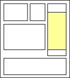
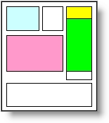
The device monitoring page is made up of default sections and customizable sections.

|
1 |
Drop-down list box where other devices can be selected. |
||
|
2 |
Device image and status LED. |
||
|
Device status LEDs |
|||
|
|
|
||
|
|
|
||
|
3 |
Device function and relevant status LEDs on buttons. |
||
|
Keys |
|||
|
|
|
||
|
|
|
||
|
|
|
||
|
|
|
||
|
|
|
||
|
|||
|
Status LED |
|||
|
|
|
||
|
4 |
Active device alarms |
||
|
Alarm priority |
|||
|
|
|
||
|
|
|
||
|
Path: |
|
|
|
|
|
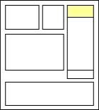
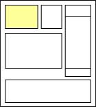
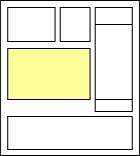
1 |
Section intended to display unit on/off status and probe variable status. Probe values also appear in the device lists (see chapter Monitoring: main page) |
|
||
|---|---|---|---|---|
|
On status LED for the unit controlled by the device |
||||
|
|
|
|||
|
2 |
Section intended to display status variables and relay status. Read-only variables. |
|
||
|
Relay/variable status LED |
||||
|
|
|
|||
|
3 |
Section intended to display the most important variables that describe the device status. Typically, they are read-only variables such as probes.
|
|
||
|
4 |
Section intended to display main device parameter tables. These variables can be edited. Click Click |
|
||
![]() See also
See also
PlantVisorPRO Locale 2.2.0 -
 (green). Device connected and on.
 (red). Device connected and at least one alarm with any priority.
 (grey). Device not connected.
 (blue). Device connected but disabled. See chapter
  /
/ /
/ Start, stop and restart the unit.
 BIOS or device application reset.
 Buzzer mute.
 Starts continuous cycle operations.
 /
/ Start/stop defrost.
 Reset all alarms.
 Start conditioning.
 /
/ Start day and night time bands.